REPORT OF THE NOVEMBER 5, 2004 ADVANCED ENGINE TECHNOLOGIES, INC. ANNUAL SHAREHOLDER MEETING
Los Angeles Airport Hilton Hotel and Carroll Shelby Enterprises, Gardena, California
The AET annual shareholder meeting of November 5, 2004 at the Los Angeles Airport Hilton hotel showed an improvement in attendence this year with some 2 dozen or so present, about 10-12 being shareholders or guests from outside of the company. Present were John Luft, COO, Neil Cummings, Secretary and Legal Counsel, the Board of Directors including Alexandria Phillips, Treasurer, and Noel Holmes. Carroll Shelby, President, and Steven Manthey were absent. Mr. Shelby had prior obligations at the SEMA show in Las Vegas, (see: http://biz.yahoo.com/prnews/041029/laf049_1.html ). Also present were lead engineer, Ian Mann, a new engineer, Mike Edwards (formerly of GE Nuclear and a friend and collaborator of Ian's), and engineering technician, Steve Wells. Michael Johnson from Australia was present for Steven Manthey. Dan Gizaw, President of Danotek Motion Technologies ( http://www.danotekmotion.com/ ) was also present to speak on Danotek's participation as a partner to develop a compact 35 KVA direct-drive generator to mate with the OX2 (see: http://biz.yahoo.com/prnews/040921/latu048_1.html ).
The formal part of the meeting was quickly dispatched with the re-election of Noel Holmes, Steven Manthey, Alexandria Phillips, and Carroll Shelby to the Board of Directors, and the ratification of the appointment of independent public auditors Singer Lewak Greenbaum & Goldstein LLP for the fiscal year ended June 30, 2004. John Luft then gave a presentation of the activities and status of AET over the preceding year.
A recap of the existing OX2 engines was given (4 engines are currently functioning):
Engine #1:
Optimum RPM 680; Torque 165 ft-lbs; HP 21; Running Hrs 10
Currently resides in Australia and no longer in use.
Optimum RPM 680; Torque 165 ft-lbs; HP 21; Running Hrs 10
Currently resides in Australia and no longer in use.
Engine #2:
Optimum RPM 650; Torque 135 ft-lbs; HP 17; Running Hrs 40
Currently in use to develop a "Fly-By-Wire" computer controlled throttle plate system.
Optimum RPM 650; Torque 135 ft-lbs; HP 17; Running Hrs 40
Currently in use to develop a "Fly-By-Wire" computer controlled throttle plate system.
Engine #2 (Turbo Configuration - 145 KPA or 7 Lbs boost):
Optimum RPM 735; Torque 215 ft-lbs; HP 30, Running Hrs 8
Optimum RPM 735; Torque 215 ft-lbs; HP 30, Running Hrs 8
Engine #3:
Optimum RPM 800; Torque 146 ft-lbs; HP 22; Running Hrs 4
Plagued with problems, resides in Australia, not running, used for spare parts and mockups.
Optimum RPM 800; Torque 146 ft-lbs; HP 22; Running Hrs 4
Plagued with problems, resides in Australia, not running, used for spare parts and mockups.
Engine #4:
Optimum RPM 1065; Torque 170; HP 34.5; Running Hrs 6
Optimum RPM 1000; Torque 174; HP 33.1; Running Hrs 6
Running, has not yet been updated or tested with new improved porting and seals, slated to be done.
Optimum RPM 1065; Torque 170; HP 34.5; Running Hrs 6
Optimum RPM 1000; Torque 174; HP 33.1; Running Hrs 6
Running, has not yet been updated or tested with new improved porting and seals, slated to be done.
Engine #5:
Optimum RPM 800; Torque 160; HP 24; Running Hrs 10
Optimum RPM 600; Torque 171; HP 20; Running Hrs 10
Has larger bore and shorter stroke to increase compression for running on LPG and other alternative fuels. Slated for LPG conversion.
Optimum RPM 800; Torque 160; HP 24; Running Hrs 10
Optimum RPM 600; Torque 171; HP 20; Running Hrs 10
Has larger bore and shorter stroke to increase compression for running on LPG and other alternative fuels. Slated for LPG conversion.
Engine #6:
Optimum RPM 960; Torque 248; HP 45; Running Hrs N/A
Recently delivered from Australia fitted into a working Lincoln Welder.
Optimum RPM 960; Torque 248; HP 45; Running Hrs N/A
Recently delivered from Australia fitted into a working Lincoln Welder.
The status of port seal materials was discussed. After experimenting with materials such as phosphorus bronze and incunel, the best seal material was found to be class 40 - gray cast iron.
John Luft discussed the improved port design in the port and combustion plates which give greater air intake and exhaust flows, and he discussed the port plate design with billet inserts which allows on-the-fly flexibility to alter port parameters. The centershaft has been a source of problems. Past centershaft crack failures have been dealt with by a complete centershaft redesign.
Part manufacturing has been completely shifted to the USA. The original engine design has about 127 parts. 33% of parts could be sourced from a parts supplier, 67% had to made. Redesign now allows about 50% of parts to be obtained from a parts supplier and 50% made, reducing costs. Parts are all now in SolidWorks CAD files, cataloged, and assembly manuals have been created. AET has its own large CNC lathe and vertical milling machine at the Gardena facility to manufacture all parts in-house that are not off the shelf.
The stand-alone 10kw generator and plans for LPG conversion have been shelved in favor of moving on to "Design Level 3". Lead engineer, Ian Mann, has now taken control over the direction of OX2 engine development. Ian decided that the small incremental steps taken to overcome design flaws and improve OX2 performance were too costly and slowing down development. He decided it would be best to start with a clean slate and come up with a new design to eliminate all of the previous problems, flaws and limitations. To this end, Ian hired his engineering friend, Mike Edwards, from GE Nuclear, and the two engineers worked together to come up with a completely new OX2 redesign. Ian estimates they are now 6 months ahead by doing this redesign.
The primary change in Design Level 3 is the elimination of the centershaft. The centershaft had been used to to move water thoughout the block; to circulate oil; to support the ramp (cam plate); and to support the inner block bearings. Design Level 3 will use a mechanical oil pump; the backplate will support the ramp; and inner block bearings will be supported by the back and front plates. The combustion chamber will have a 50% increase in airflow. The piston plate will be changed from aluminum to a cast steel I-beam design which will have a 10X greater load capacity with a weight increase of only 1 pound. The parts to assemble a piston plate will be reduced from 72 to 16 parts. The cylinder bores will be increased from a prior limitation of 69.5mm to 80mm. The engine capacity will increase from 1.2 liters to 1.8 liters with no overall increase in engine dimensions. There will be two sparkplugs firing per cylinder to increase burnrate (i.e. a total of 4 plugs). Rockers will be beefed-up and improved. (Rockers are like little seesaws that pivot and go inbetween the piston plates, the piston plates ride the "seesaws." As one piston plate goes up, the rockers pivot and push down on the other piston plate and vice versa which serves to help hold the piston plates against the ramp or cam. 8 rockers are seated radially into the face of the cylinder block between the 8 cylinder bores and push down on the piston plates against wearpads located between the pistons.) Off the shelf parts will be 36, manufactured parts 21, for a total of 57 parts compared to the 127 parts required by the previous design.
Design Level 3 has already been laid out in CAD files and casting patterns are being made. Some castings and parts have already been produced. Some of these parts and patterns were on display at the meeting.
John Luft then introduced Dan Gizaw of Danotek and turned the meeting over to him. Located in Ann Arbor, Michigan, Danotek's mission is to develop innovative electromechanical systems for energy and transportation industries. Its main products are motors, generators, power electronics and controls. As an example, Danotek is developing small efficient brushless motors for the automotive industry. Danotek has over 100 patents.
For AET, Danotek is developing a NdFeB permanent magnet DC generator (16-poles according to Ian Mann) that is liquid-cooled (cooling shared with the OX2 and the electronics). The diameter is to be 380mm (15 inches) and length 330mm (13 inches). Its maximum weight, 100kg (220 Lbs) Digital power electronics will shape and control the electrical characteristics and provide AC output. It will produce 35 KVA at 400/277 VAC, 50/60 HZ, and handle a 200% overload for 1 second and a 150% overload for 10 seconds. It will have a 94% efficiency. It will attach directly to the OX2 in place of the backplate to be directly driven off the OX2. Multiple gen-sets can be daisy-chained together for higher power requirements. As OX2 power output improves, it will be possible to have up to a 50 KVA gen-set in the same configuration.
Danotek began the project in June, has completed the design, and has begun to look for and order parts. They expect to begin benchtesting the generator by February 2005. Testing at the system level is expected to begin in March or April depending on the success of integrating generator with the OX2. Final commissioning is expected around May or June 2005.
AET expects to have 3 commercial applications ready for market over the next year: the integrated gen-set with Danotek; the OX2 integrated Lincoln Welder; and OX2 technology available to any company wishing to incorporate it in their own generator systems.
The meeting concluded and everyone was invited over to the AET facility at Carroll Shelby Enterprises in Gardena. The building housing Carroll Shelby Enterprises has been remodelled and enlarged since the last OX2 demonstration, November 20, 2001. Walking back to the AET facilities, one passes by a huge collection of motorcycles, plus a few Shelby Cobras and even some vintage disassembled airplanes. Tons of Goodyear racing tires are piled on the floor. Reaching the backroom, AET shares the room with tons of machinery used to produce the Shelby 427 FE engines which lay in quantity on the floor in various unfinished states of manufacture. AET's HAAS SL-30 CNC lathe and HAAS VF-4 VMC vertical milling machine stand amongst the machines. ( http://www.haascnc.com/products/ ) The dynamometer rooms, once separated by a wall, are now combined into a single area with a control panel for each of the two SuperFlow SF-901 dynos in one control room with viewing windows looking into each of the two dyno rooms. ( http://www.superflow.com/products/ )
One dyno room held OX2 engine #4 which was demonstrated running. The second dyno room held OX2 engine #2 which was also demonstrated running. Engine #2 is fitted with a "fly-by-wire" throttle plate that was configured to maintain, by computer, constant RPM regardless of load, 700 RPM in this case. Following the demonstration of engines #2 and #4, attendees went outside to see a running demonstration of engine #6 integrated into a Lincoln Welder. OX2 engine #6 ran just fine, but, unfortunately, the Lincoln Welder refused to produce electrical power, and AET was unable to demonstrate the unit actually welding as planned. So, in all, THREE OX2 engines were up and running at the demonstration!
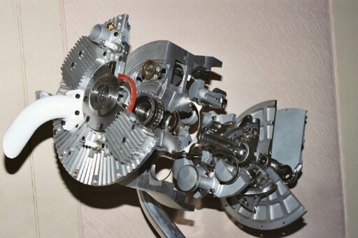
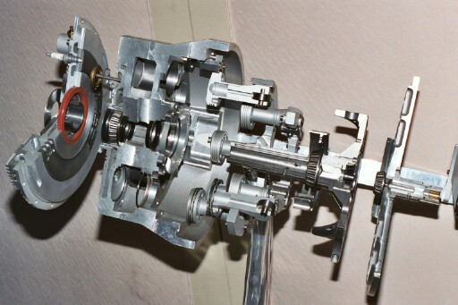
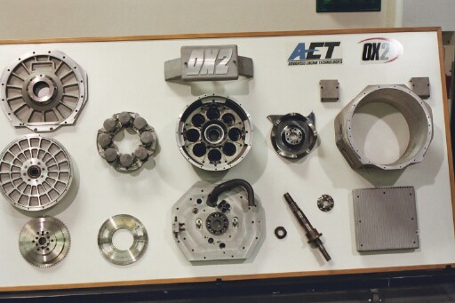
Above are photos of the OX2 cutaway model taken at the November 11, 2003 meeting and a display board at the Gardena facility showing OX2 engine parts. The part designs shown are now out of date.
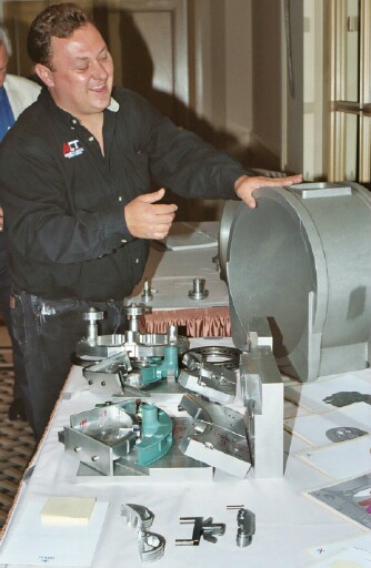
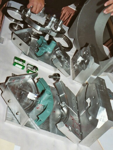
Ian Mann is shown unveiling OX2 Design Level 3 parts, patterns, and castings.
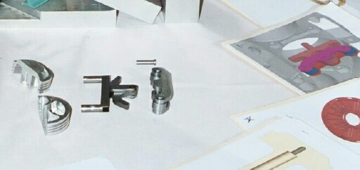
Above are a piston casting, an old rocker of previous design is in the middle, and a new rocker designed with rollers is on the right. On the far right is a CAD drawing showing how the 8 new rockers will mount into slots on the face of the cylinder block between the cylinder bores.
This is an old piston plate showing the rectangular rocker wearpads that produced problems by coming loose during the engine test runs.
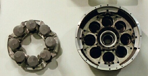
Here, with the two piston plates nested together, the 8 pairs of rocker wearpads are clearly visible between the pistons. On the surface of the cylinder block are 8 radial slots (with holes on each end) between the cylinder bores where the 8 old design rockers are inserted. The rockers "ride" the piston plates on the wearpads.
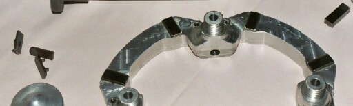
Above are the patterns and plastic castings of the new Design Level 3 pistons plates, an old piston plate is shown in the background. These will be steel castings in the finished product. Note the I-beam design. Also note the raised circular pads on either side of the piston holders. These new integrated rocker wearpads replace the old rectangular wearpads.
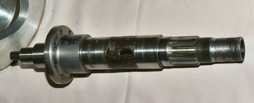
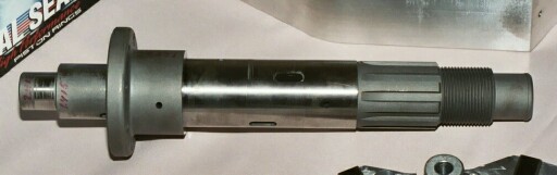
The centershaft has been a problem in the past, with shear stress cracks and cracking in the splines. The centershaft on top is the old design. Below is a new centershaft designed stronger to eliminate the stress cracks. Note its beefed up splines. Design Level 3 will completely eliminate the centershaft.
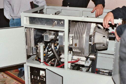
This photo from the November 11, 2003 meeting shows the 10 KW stand-alone OX2 gen-set. This project has been shelved in favor of moving on to Design Level 3 and the Danotek integrated gen-set.
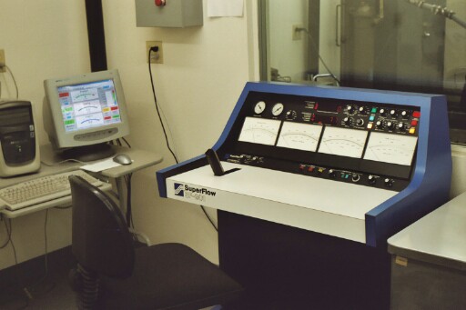
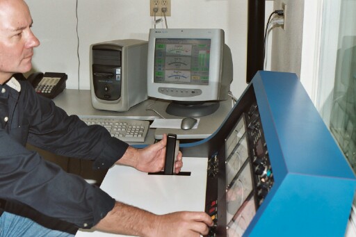
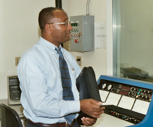
This is the SuperFlow SF-901 control panel for one of two dynamometer rooms at the Gardena facility. Steve Wells is shown running OX2 engine #4 at the demonstration.
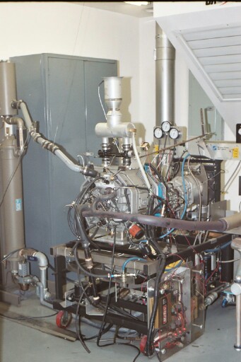
Above is OX2 engine #4 running on the dyno.
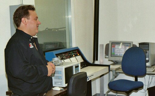
Ian Mann discusses the "fly-by-wire" throttle plate being tested on OX2 engine #2 in front of the control panel for the second dyno.
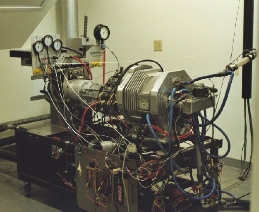
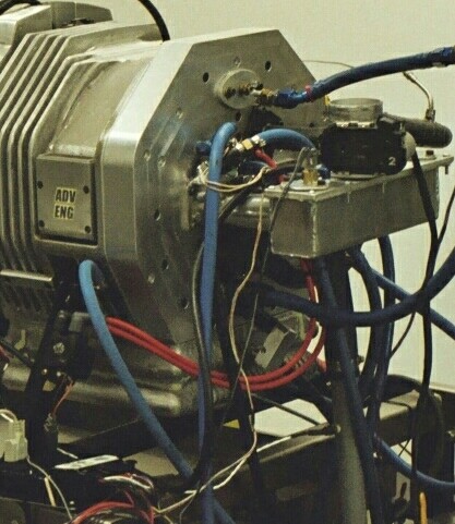
Above, at the top, is OX2 engine #2 in the second dyno room. In the closeup below, the "fly-by-wire" throttle is seen in the upper right with its wires running to the controller in the lower left.
Daniel Gizaw, President of Danotek Motion Technologies.
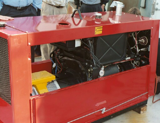
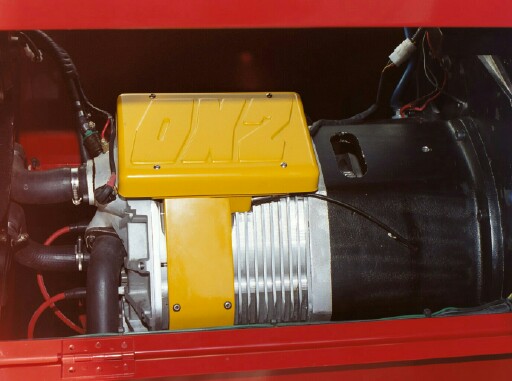
Here is OX2 engine #6 installed in a Lincoln Welder.
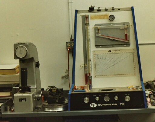
AET is equipped with a metal hardness tester and a SuperFlow 110 flowbench for research and development.
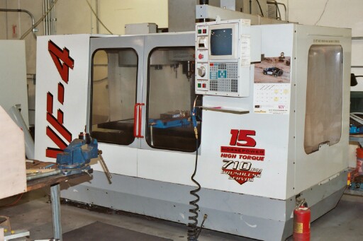
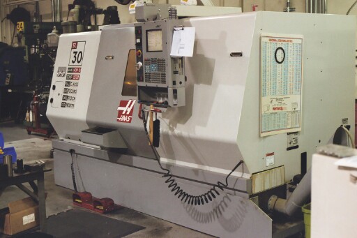
Shown are AET's HAAS VF-4 VMC vertical milling machine and the HAAS SL-30 CNC lathe which can machine virtually all of the parts needed for the OX2.
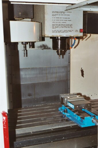
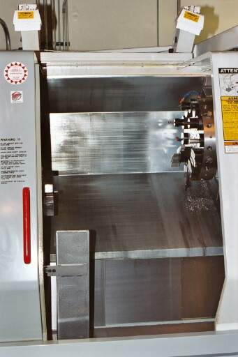
Looking inside the HAAS VF-4, top, and inside the HAAS SL-30, bottom.